Introduction
Earth is considered as most inert material. However, due to its low tension carrying capacity, designers are compelled to increase the tensile strength of earth/soil by providing reinforcement (metallic/ polymeric). The incarnation of the reinforced soil retaining systems provide extra tensile strength to soil and serves our purpose (Schlosser 1988). In last decade, reinforced earthwork or soil wall has gained popularity in India, particularly in flyover approach construction due to their relative advantages over conventional retaining walls. Reinforced soil walls are superior both technically and economically in comparison to the conventional retaining wall construction. Construction is simple and requires less working space. Due to its compact design, reinforced earth retaining walls can be constructed in congested areas too (Durukan,1992). The walls are aesthetically more appealing. In reinforced soil system pre-cast panels are erected vertically by providing reinforcement periodically as per designs. Under the load of earth above the reinforcement gets active and the entire system readily takes tension Construction of Reinforced Earth Wall involves three major tasks:- Precast panels.
- Erection of panels
- Reinforced earth work.
Precast Panels
Precast work starts with working out the quantities of the number of panels required for the given project. Since setting up of casting yard is capital intensive, it is desirable to setup common facility for different work packages.Setting up the casting yard
Quantum of work undertaken determines the dimensions of a casting yard. Often space constraint restricts the storage space for precast panel resulting in smaller buffer quantities of precast panels. Casting yard consist of following main components: Concrete pedestals or slippers on which the moulds are fixed for casting the panels; reinforcement yard; stacking yard; lab testing and supporting amenities. Batching plant for concrete is usually common with the project concrete requirements.Moulds for casting concrete panels
Depending on the quantum of panels to be casted, the project schedule and desired steel moulds are fabricated. Moulds are setup on concrete bed with allowable tolerance. Bottom face (i.e. the outer face when erected) is permanently fixed and may have desired pattern as they face exterior, whereas the sides of the moulds are provided with nut-bolt mechanism for ease of assembly.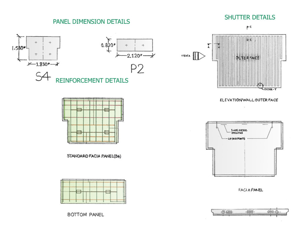
Casting of the panels
Casting of the panels involves preparation of reinforcement cage, application of shutter oil, placing of the reinforcement cage, placing the panel accessories, pouring concreting-compaction, marking, removal of side shutter, lifting-stacking for curing of panels, and finally stacking curing is over.Stacking of the cast panels
After requisite curing period, panels are shifted to stacking area either using crane or gantry. Stacking of the cured panels happens in the stacking yard, where precautions are taken to prevent breakage and overloading. No more than six panels should be stacked, the connectors of the panels should be taken utmost care of to ensure they are not damaged; the I-bolts given must face same side to facilitate easy transport of panels.Transportation of Panels to Site
Upon receiving requirement from site, the stacked panels are transported on site using trailers. Following precautions will ensure the durability of panels: Place the bottom panels on rafters, no more than four panels in a row; at-least 200 mm gap to be maintained using wooden/concrete blocks; the panels must be chained while transporting; the speed of truck must be such that the panels are not damaged due to jerks.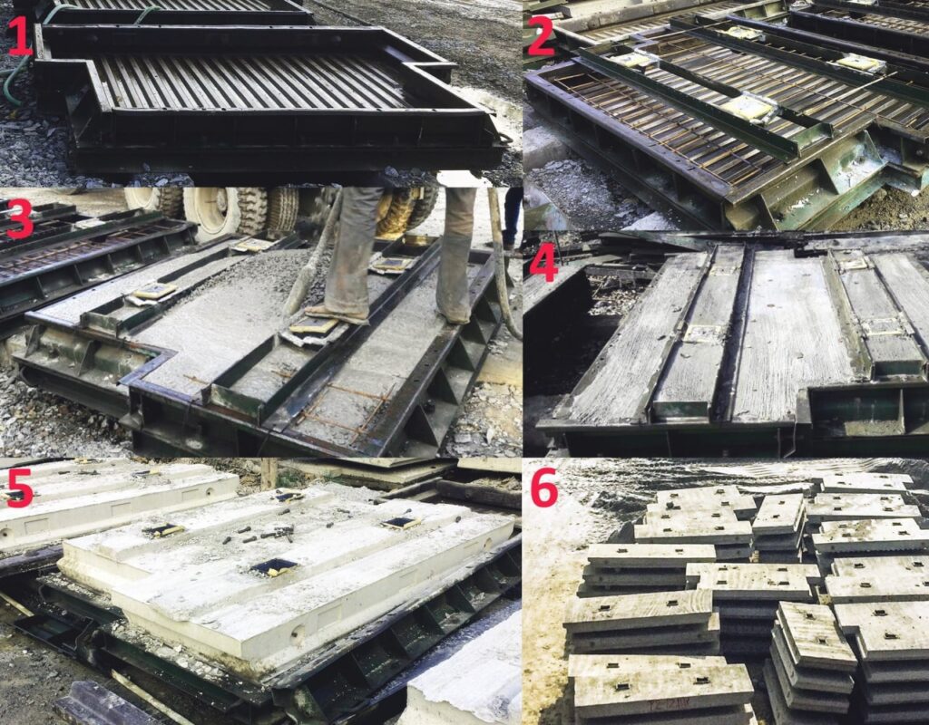
- Moulds are applied shutter oil.
- Accessories adjusted.
- Concreting commences.
- After compaction and finishing.
- De-shuttering.
- Stacking.
Erection of Precast Panels
Level 1: Line-out, survey, excavation, dressing and PCC
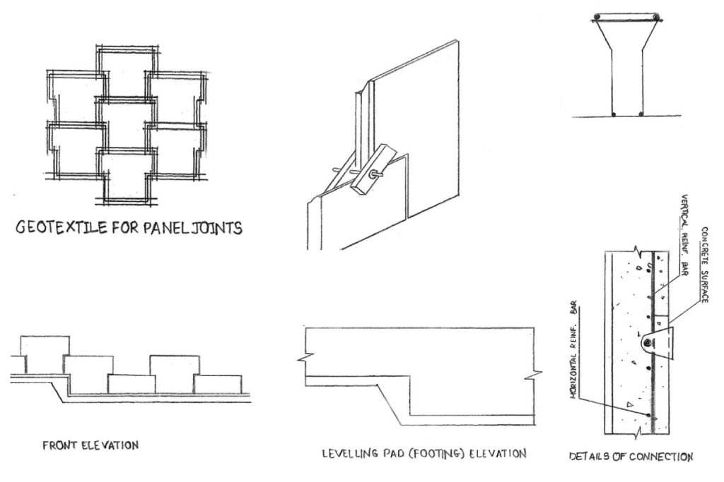
Surveyor provides coordinate so that line out can be carried out for excavation work. Simultaneous check of level is carried out at interval of 1m using auto-level during the excavation. Excavation is carried out by. Dressing and levelling of excavation soil is carried out by soil compactor. Once again survey coordinates are established along with checking the exact levels for PCC work. PCC work with specified thickness and width is laid on which a key is provided on the outer edge for holding the panels erected.Level 2: Line-out, survey, erection of panels, sand filling, para-web installations
Once PCC is completed again coordinates are marked on it and now final line out is carried out for erection of panels. Bottom panels are erected leaving appropriate space for placing panels above. Placing is carried out using hydra. Placing proceeds from the abutment side. Props are erected temporarily on the outer face to provide lateral stability.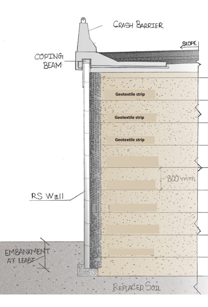
Alignment Check: Spacers of required dimensions are prepared to check the space between two panels. Top of each erected panel is checked using spirit level to ensure that panel is horizontal. A crow bar is used for minor adjustments.
After the alignment check, standard panels are placed above the bottom panels. Temporary hard wood wedges are firmly placed in the vertical joints near the bottom of panel being erected with shoulder of the below one. Wooden wedge spacers are used at horizontal joints too. After placing all the panels, again all the three alignment checks are performed.
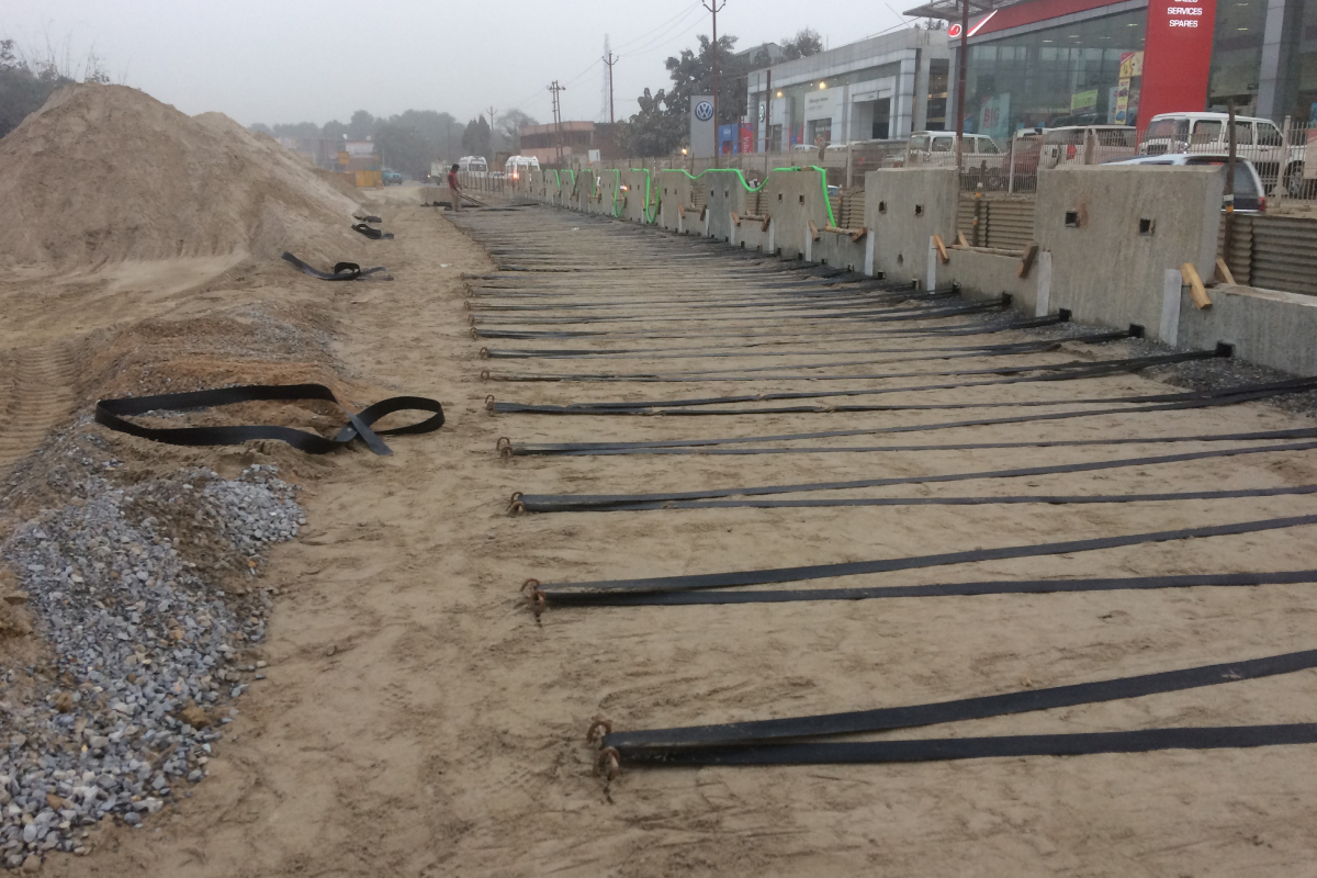
After both horizontal and vertical alignment, non-woven geo-textiles are glued at exposed joints. After erection of first layer, approved material of desired density is used to fill up the layers.
Filling and compaction happens in layers of 200 mm each. Once compaction covers the sand/earth-fill, further sand filling happens followed by insertion of 10-20 mm aggregates in width of 250 mm. Gravel filling happens amongst panel and sand layers for purpose of storm water draining.
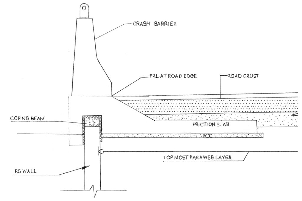
Level 3: Dirt wall construction, coping beam construction, pavement work
Dirt wall stands on the abutment and is casted simultaneously when RS wall construction goes on. Once panel laying activity completes, coping beam is constructed (figure-5). After that road work commences as per the drawing specification.